Written by: Zacharie Doerr, P.Eng, Project Manager of the BSS Group & Kyle Silliker, P.Eng, National Director of the BSS Group at Pinchin Ltd.
This article was originally published in the Spring 2018 edition of Pushing the Envelope Canada, which is printed twice per year by Matrix Group Publishing Inc. for the Ontario Building Envelope Council. It has been reprinted with permission.
In colder climates, we typically design for cold on the outside of our buildings and walls. But what if the cold walls are on the inside of the enclosure and interacting with the indoor environment?
We’re not talking about our southern neighbours in warmer climates with indoor air conditioning. We’re referring to our local ice rinks, curling clubs, and walk-in freezers, in which condensation and mould growth can become an issue due to inadequate thermal barriers surrounding indoor cold areas.
These instances represent unique building science challenges when different climates interact within the building and across the building enclosure. It can be easy for consultants and designers to overlook these interior enclosures since they are not part of the traditional building envelope. However, the potential issues that could arise in a building with indoor microclimates can be resolved or potentially avoided altogether with the proper considerations and the right approach during the design phase.
DESIGNING AND MAINTAINING THE ENVELOPE
Temperature differences between our interior ice rinks and their adjacent heated spaces rival those that we see between our indoor conditions and the exterior environment in the winter months; therefore, we need to use the same care in designing and maintaining the envelope between these spaces, as we do with our exterior walls.
Another common, yet extreme condition is the change in temperature and humidity in changerooms and showers that share a wall with an ice rink. Typically, we can control the humidity or source of moisture in these situations through active dehumidification. But in some of these situations, our warm side of the wall is actually outside. We run into this situation frequently with crawls spaces and parking structures below our freezer and coolers in retail spaces.
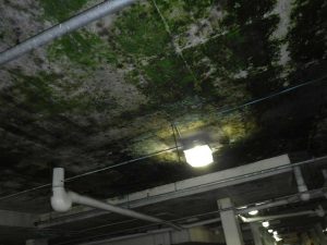
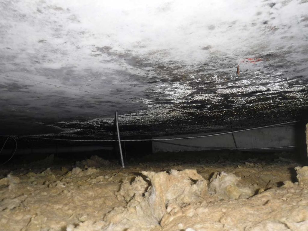
On these cold walls, the issue we run into is condensation. Unlike our typical outside wall, indoor walls have nowhere to drain excess water. As can be seen in the photo (fig.1), with a bit of condensation comes mould.
In theory, the solution is simple—if you can’t control the humidity, control the temperature. More specifically, control the surface temperature of the cold wall and maintain it above the dew point temperature. This can be accomplished through additional insulation or active heating. If increasing the insulating values, don’t forget about thermal bridging. Examples of thermal bridges include concrete slabs which support walk-in freezers, steel structural members, and wood structural members. Other design criteria to be considered are the air and vapour barriers. The following are some case examples highlighting these items.
CASE 1: ICE RINKS
Our local ice rinks are great examples of cold walls located within the building enclosure. Humidity control within the ice rink is typically included in the HVAC system to minimize condensation and prevent energy loss at the ice pad’s refrigeration system. Adjacent change rooms, offices, skate-shops, and viewing areas are maintained at typical indoor conditions. The change rooms and showers frequently experience high humidity conditions, and the partition walls between the rinks and these rooms have become cold walls, but are often not designed as such.
In a shower or change room, it is difficult or cost-prohibitive to adequately control the humidity, so we try to control the surface temperature at the envelope between the heated and unheated space. Maintaining a surface temperature above the dew point is key to mitigating condensation and mould. Actively heating the surface of the cold wall can be effective but not necessarily efficient. High installation costs and ongoing energy costs must be considered. The best and most cost-effective way to maintain the surface temperature is through insulation. Thermal modelling and dew point analysis are great tools to understanding the required amount of insulation in order to prevent condensation.
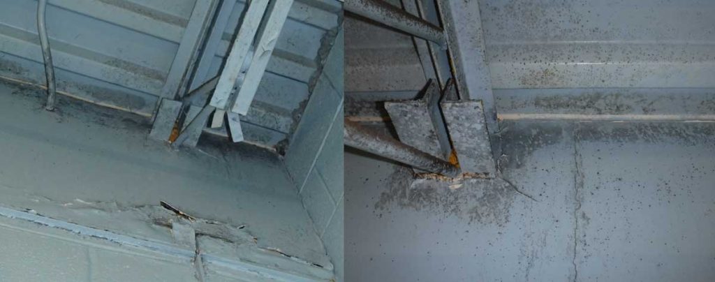
Similar to our exterior walls in a cold climate, we want the insulation on the cold side of the wall to prevent condensation on the warm side of the wall. Conveniently, this also prevents thermal bridging from the steel ceiling joists that are common in these buildings. These steel elements are highly conductive thermal bridges that we must consider during the design process. As you can see in the photos above (fig. 2 & 3), condensation and mould were identified surrounding the steel members on the warm side of the cold wall. On the other side of this wall is the cold ice rink.
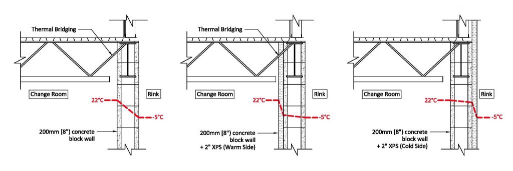
In this case, insulating on the warm side (change room) can provide an adequate thermal barrier to prevent condensation throughout most of the assembly, but it does not prevent thermal bridging and condensation at the steel structures. Continuous insulation on the cold (rink) side of the wall maintains the wall assembly and structural members (thermal bridges) above the dew point (fig. 4).
CASE 2: WALK-IN FREEZERS
Walk-in freezers are another good example of a cold room within a building. Manufacturers have effectively designed the walls and ceilings of the pre-manufactured freezers to mitigate condensation. When the envelope of the walk-in freezer is adjacent to conditioned space within a building, the conditions are typically controlled and reasonably manageable.
More recently, we’re seeing new freezers with insulation on all six sides, but many of the older units are only insulated at the walls and ceilings. Typically, the floors are supported by a highly conductive floor assembly, such as a concrete slab. This is compounded when the concrete slab is exposed to the outdoor / unconditioned space, such as a parking garage, wet basement, or crawl space. Condensation and subsequent mould growth has been observed at these locations.
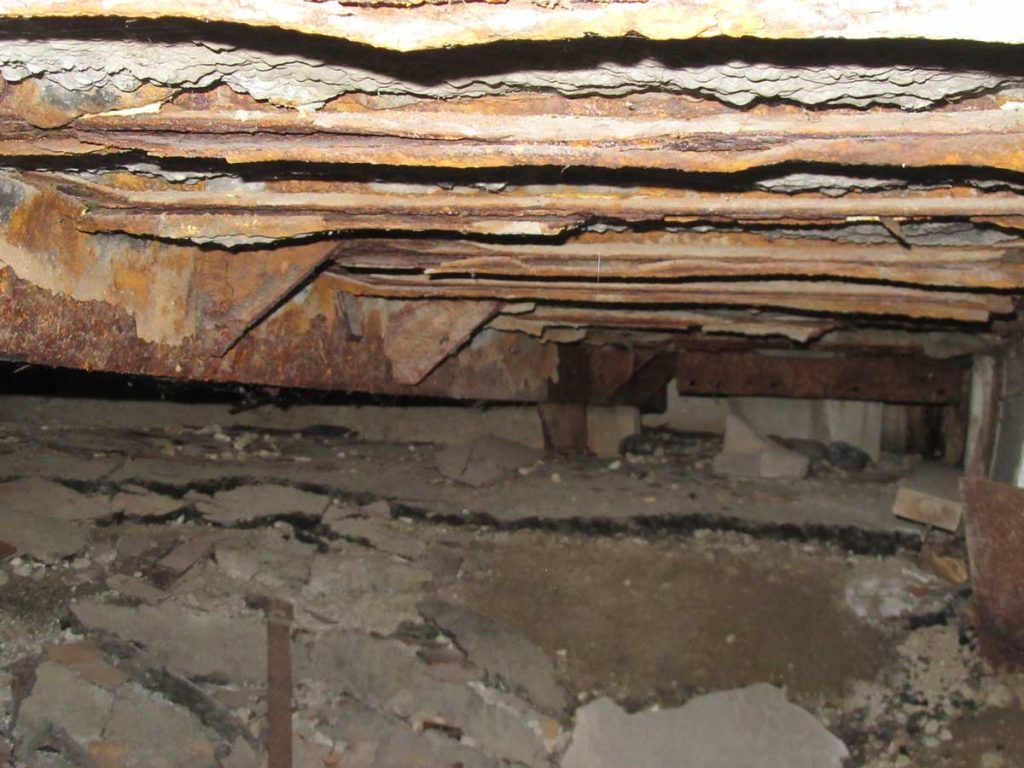
Many things can happen when we have condensation at the underside of the floor assembly, including:
- Rusting and deterioration of steel pans at the underside of a concrete deck (fig. 5);
- Mould growth and rot on wood-framed assemblies;
- Concrete damage due to freeze-thaw cycles; and
- Mould growth on concrete, even if there isn’t an abundance of organic material (fig. 6).
Retrofitting the floor assemblies can be a challenge. Do we insulate inside the freezer or the underside of the floor assembly? What insulating material to use? What R-value? If we’re insulating at the underside of the floor assemblies, how far do we insulate beyond the freezer footprint?
Two-dimensional modelling software can be a great tool to eliminate guesswork and can help validate proposed designs. We must also understand what conditions the cold wall will be exposed to. Modelling shows, as one might expect, that insulating at the interior of the freezer’s floor performs better than insulating at the underside of the floor assembly. The floor assembly is maintained at a warmer temperature, less insulating material is required, and there is better thermal performance (Fig. 7).

Insulating from the inside of the freezer may not be feasible for several reasons—perhaps the owner(s) will not accept raising the height of the freezer floor; the floor assembly’s structural requirements do not allow the floor to be sumped; the installation is cost prohibitive; or maybe there are shut down restrictions.
When insulating at the underside of the floor assembly, we must consider and account for any thermal bridging from those pesky structural members. Open web steel joists and concrete slabs are great at conducting heat.
Other items to consider when insulating at the underside of a concrete slab include your air and vapour barriers within your floor assembly. Simply providing the required insulation does not guarantee that condensation will not form at the underside of the concrete slab (fig. 5).
In this situation, insulation was installed, but unforeseen air transfer into the ceiling plenum contributed to condensation at the underside of the concrete deck.
Also, ensure that any remaining moisture within the floor assembly has been removed before insulating. Encapsulating damp wood structures with spray foam can lead to rot. Insulating wet structures adjacent to freezing conditions can lead to expansion damage at the assemblies.
CASE 3: WALK-IN FREEZERS ALONG AN EXTERIOR WALL
There are challenges associated with addressing a walk-in freezer that is located directly adjacent to an exterior wall. This configuration is typically done to effectively use the available floor space. This situation presents a challenge in the winter when you have both cold on the interior and exterior of the wall(s). This situation does not allow heat from the building to reach the interior face of the wall assembly. In addition, it is very difficult to provide a reliable and continuous vapour barrier between the wall and the freezer. Not only is this a tricky one to install, it also presents a problem with monitoring whether we are getting condensation in this high-risk area.
As you can see from the diagram (fig. 8), our wall assembly is well below the dew point of the interior space during the dead of winter. In fact, there is risk of frost and ice buildup in this wall if the warm and humid indoor air comes into contact with either cord surfaces.
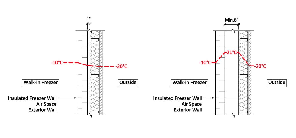
So, how do make this vapour barrier continuous? Easy, you don’t even try. Instead, the most effective way to ensure that we limit condensation in this space is to move the freezer away from the wall and provide heating and ventilation between the freezer and the wall. If possible, you will want to get approximately 400 millimetres (16 inches) of space between the two walls to allow for inspection and maintenance. If your client doesn’t want to give up that precious floor space, then go with at least 150 millimetres (six inches) to allow for a visual inspection.
DESIGNING FOR BUILDINGS WITH MICROCLIMATES
As consultants, there are other assemblies outside of the traditional building envelope that require our attention and can create challenges. The building science principles involved in resolving or preventing these issues are common, but the wall conditions are not common. When designing a building with indoor microclimates, remember to consider the indoor cold walls and their unique design requirements.
Zacharie Doerr, P.Eng, is project manager for the Building Science and Sustainability Group at Pinchin Ltd. He has received his Master of Applied Science and his Bachelor of Applied Science in Mechanical Engineering, both from the University of Ottawa.
Kyle Silliker, P.Eng, is national director of Pinchin Ltd.’s building science and sustainability group. He received his Bachelor of Applied Science degree in Civil Engineering from the University of Toronto. He is a leader in the building science industry and has 10 years of experience working with architects, developers, and property managers.